
The first instrument we looked at was a toy drum, back in section 2.2. Now it is time to look more carefully at drums. The majority, like the ones in the drum kit seen in Fig. 1, are not tuned to any definite pitch. They are designed to make different sounds, of course, and drummers exploit these differences for musical effect. But there are also tuned drums, and we will look at two varieties using different principles to achieve tuning.

The family of mode shapes of an ideal drum was shown in section 2.2, and is reproduced here in Fig. 2. The theory behind these mode shapes and natural frequencies is presented in the next link. Each mode shape involves variation with polar angle $\theta$ around the drum which takes the form $\cos n \theta$ or $\sin n \theta$, where $n$ must take one of the values 0,1,2,3… Each row of Fig. 2 corresponds to a different value of $n$, starting with $n=0$ on the top row. For this value, $\sin n \theta =0$ but $\cos n \theta = 1$, so these modes are axisymmetric.
For all the higher values of $n$, $\cos n \theta$ and $\sin n \theta$ both make sense, so each of these modes appears as a degenerate pair with the same natural frequency: the tecnically-minded could look back to section 2.2.4 for an explanation of what that means. But any real drum will have some departure from perfect circular symmetry: the mass distribution and the tension will never be perfectly uniform. The result is that if a measurement is made, these pairs of modes will normally be slightly separated in frequency and show up as double peaks in a frequency response plot.
The variation of each mode shape in the radial direction is given by something called a Bessel function, a different one for each value of $n$. The relevant Bessel functions are usually written $J_n$; plots of the first few can be found in the link above.
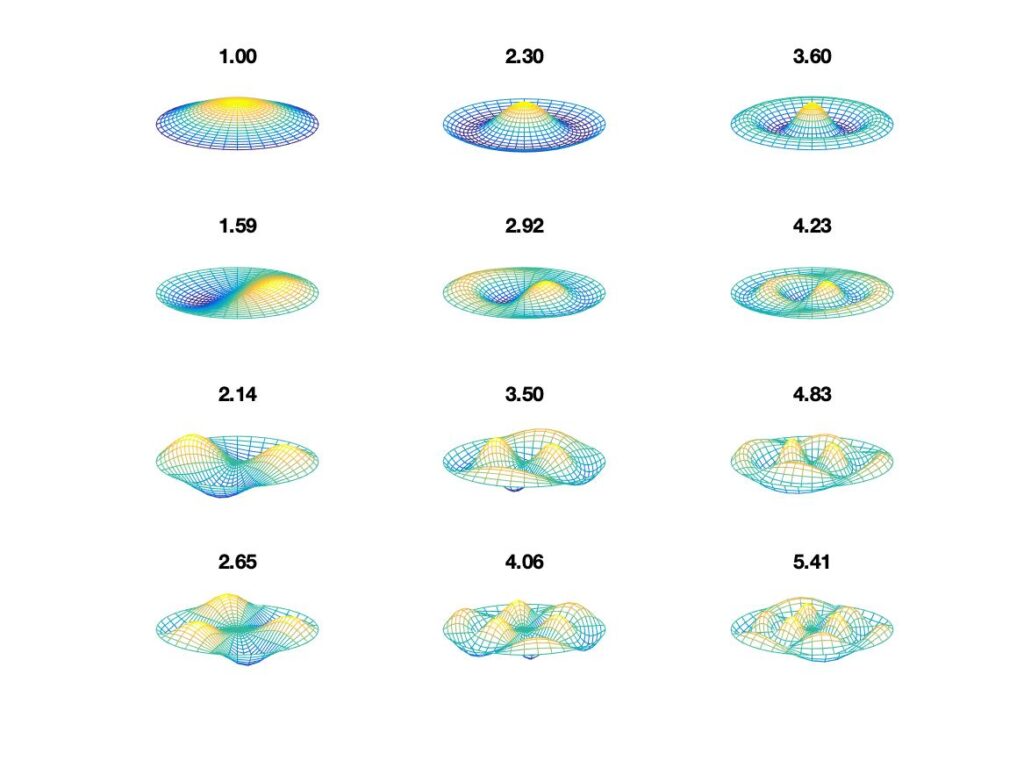
Figure 2: The vibration modes of an ideal circular drum, with no allowance for loading by air in contact with the drum skin. All modes in a particular column have the same number of nodal circles, while all modes in a given row have the same number of nodal diameters. The first few are shown here: the pattern continues indefinitely to the right and downwards. Above each mode shape is listed its natural frequency, relative to the fundamental mode.
The frequency ratios in Fig. 2 do not reveal any obvious harmonic relations between the natural frequencies. That remark would still be true if we took account of an important factor that hasn’t been mentioned yet. Drum membranes were traditionally made of natural skin of one kind or another, but most modern drums use a synthetic material familiar from trade names such as Mylar. A Mylar drum head will only weigh a few grams, sufficiently light that we cannot ignore the influence of the air in contact with the membrane on both sides. A natural skin head would be somewhat heavier, but still very light compared to the other percussion instruments we have looked at, or the wooden soundboard of a typical stringed instrument.
Air motion is important for two reasons. The purpose of the drum is to make audible noise, so of course the air carries sound waves away from the vibrating drum. But there is also kinetic energy associated with local movement of air close to the membrane. The inertia associated with this kinetic energy will increase the effective mass per unit area of the membrane, and thus reduce all the natural frequencies compared to the simple theory presented in the link above. The effect depends on the wavelength and other details of the mode shape, so it is different for each mode and therefore changes the frequency ratios.
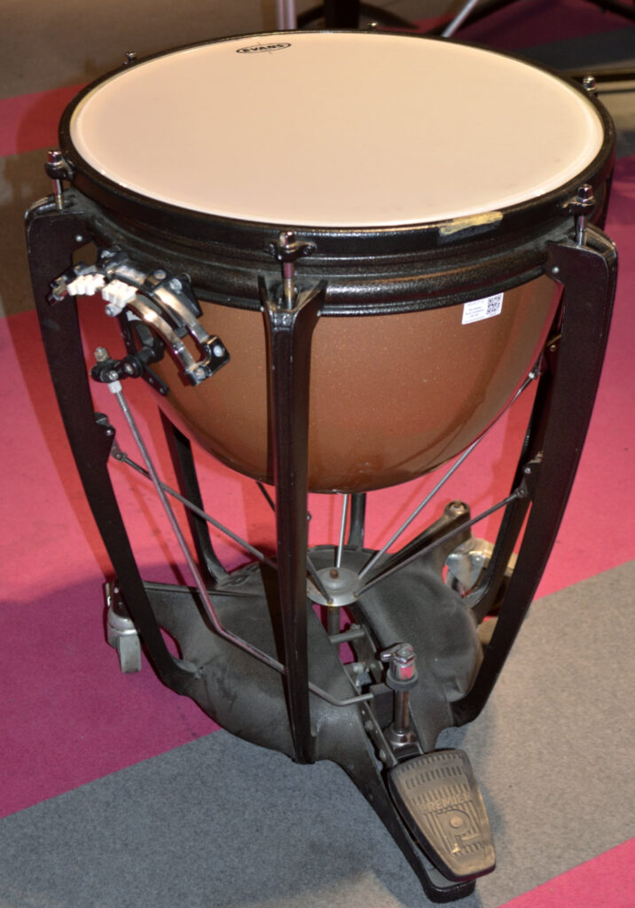
This added-mass effect from loading by the surrounding air does not, of itself, create harmonic relations between the natural frequencies. However, the first of our tuned drums, the orchestral kettledrum, makes ingenious use of air motion in order to do exactly that. The shape of the “kettle” beneath the drum membrane (see Fig. 3) has been developed over the centuries to modify and control the added mass associated with air motion, by interaction with internal acoustic resonances of the cavity. The result is that a few of the natural frequencies fall close to harmonic relationships. A skillful percussionist will fine-tune these relationships by careful adjustment of the tension distribution in the membrane.
We can illustrate the results with some measurements and synthesised sound examples. Christian et al. [1] measured natural frequencies of a kettledrum membrane both with and without the presence of the kettle. The case without kettle includes an effect of air loading, so the frequencies are already different from the ideal case analysed in the link above. Adding the kettle causes further change of these frequencies.
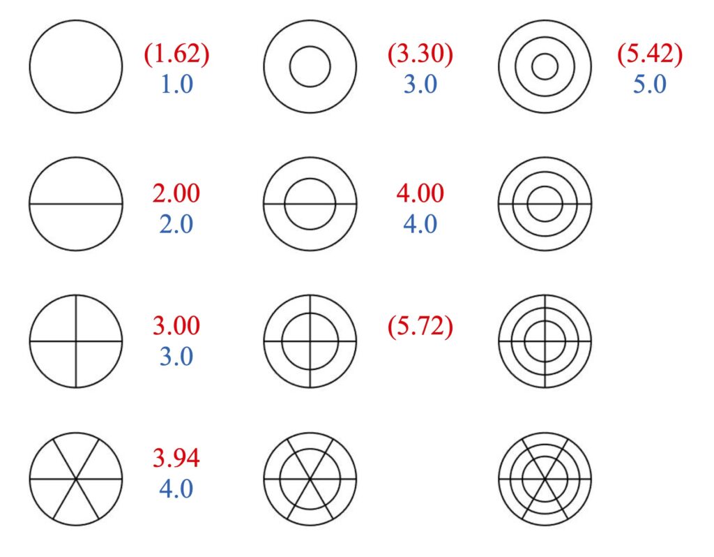
The most important frequency ratios for the final case, with the kettle, are summarised in the red numbers in Fig. 4. These are expressed as ratios relative to the mode with a single nodal diameter, but for reasons that will rapidly become apparent this mode is given the nominal frequency 2. It can be seen in the figure that three other modes fall into harmonic relations to this one, with relative frequencies close to 3 and (for two different modes) 4. So we have harmonic relations, but this is another case of a “missing fundamental”: there is no mode with frequency 1 in these terms. Furthermore, the axisymmetric modes in the top row are not tuned, so they will tend to detract from the sense of definite pitch. For that reason, a percussionist does not hit a kettledrum near the centre, which would maximise the sound from these modes while giving little sound from the tuned modes (which all have at least one nodal line through the centre).
To illustrate the consequences of these various different sets of natural frequencies, three sound examples appear below. Sound 1 uses the frequency ratios of the ideal membrane without any influence of air, as in Fig. 2; Sound 2 uses the measured frequencies from Christian et al. [1] without kettle, and Sound 3 uses their measured frequencies with the kettle. Apart from the different frequency ratios, all three sounds use identical parameters. The same set of modes is included in each case, and the reference mode with one nodal diameter is assigned the frequency 172 Hz to match the measurements; all modes are given a Q-factor of 100; and all are given the same amplitude except that the lowest mode has amplitude reduced to 30% of this value as a crude representation of the fact that a performer would try to de-emphasise that mode. As with all the sound examples in this chapter, the intention is not to produce the most realistic synthesis of a drum sound. Rather, the intention is to allow a clean comparison of the effect of changing the frequency ratios with the minimum of complicating factors.
To my ears, at least, the sounds are all reasonably drum-like. The differences are fairly subtle, but I could hum the pitch of Sound 3 with confidence, whereas the other two are more ambiguous.
So the kettledrum has illustrated one way to apply some acoustic engineering to the design of a drum in order to produce a sound of definite pitch. But it is not the only possibility: the champion makers of tuned drums come from India. Several types of Indian drum use the same trick for tuning. The most well known of these is the tabla, shown in Fig. 5. Both drums in this picture have a black patch on the membrane. This patch is the result of the drum-maker painstakingly applying layer after layer of a paste made from over-cooked rice blended with a heavy black powder containing manganese and iron oxide. By careful distribution of this progressively added mass, they manage to tune at least 8 of the natural frequencies into harmonic relations: twice as many as in the kettledrum.
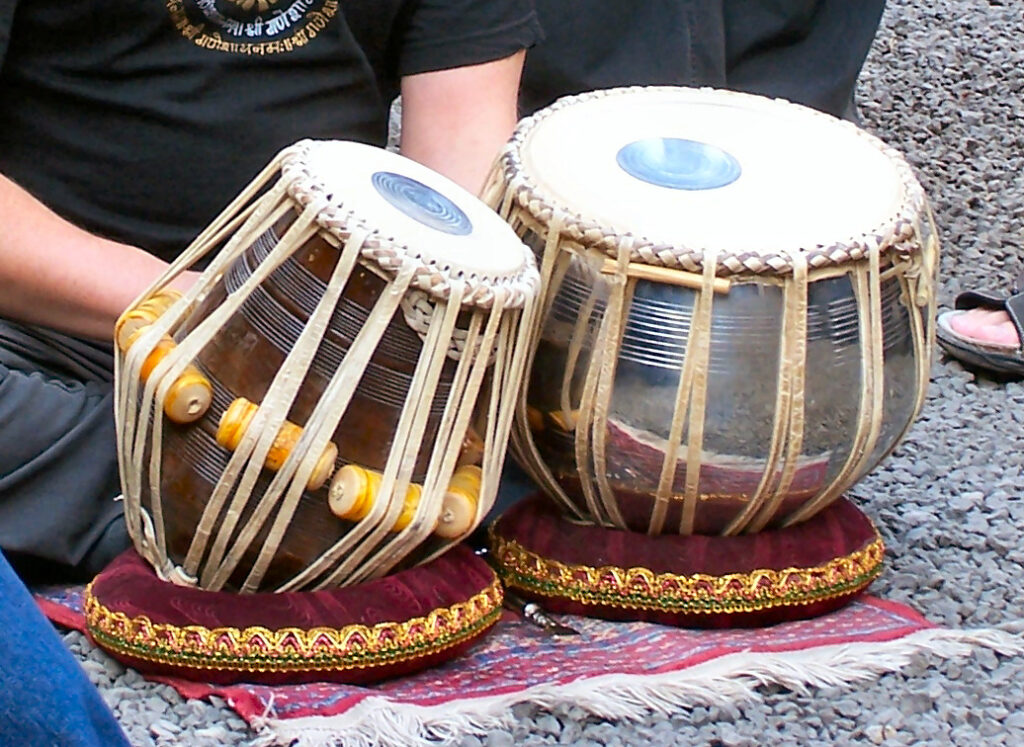
The smaller of the pair of drums in Fig. 5 exhibits the most impressive level of harmonic tuning. The extraordinary number of tuned modes in such a drum was first discovered by C. V. Raman [4], who also became India’s first Nobel prizewinner for his work on light scattering. We will make use of some more recent results: Rossing and Sykes [3] followed the process of tuning a Southern Indian drum called the mridanga, which exhibits the same pattern of tuning that Raman found in the tabla. They recorded the frequencies of major peaks in the sound of this drum throughout the process, which involved over 100 separate layers of paste being applied!
The key conclusion of their study is shown in the blue numbers in Fig. 4. In addition to the four modes that were tuned in the kettledrum, the three axisymmetric modes in the top row were tuned. At least one other mode outside the range shown in Fig. 4 was also tuned: the mode with four nodal diameters, which would be the next one in the first column, was tuned to frequency 5 in the terms of this plot. Within the frequency range of these tuned modes, there are no untuned modes. Furthermore, the combination of frequencies no longer has a “missing fundamental”.
Using these frequencies in a synthesis exactly like those for the previous sound examples (except that the amplitude of the first mode is now the same as all the others) gives the result in Sound 4. With so many tuned modes, and with no untuned modes included, the sound is not immediately recognisable as a drum of any kind. Perhaps it does not sound entirely like a tabla either — but that is partly because this pattern of repeated slow notes left to ring on is not at all in the typical musical style of tabla playing. More normal would be a blizzard of notes in complicated rhythmical patterns, played with the fingertips and making use of the variety of sound possible by striking in different positions on the drum head.
[1] R. S. Christian, R. E. Davis, A. Tubis, C. A. Anderson, R. I. Mills and T. D Rossing; “Effects of air loading on timpani membrane vibrations”, Journal of the Acoustical Society of America 76, 1336–1345 (1984)
[2] Neville H Fletcher and Thomas D Rossing; “The physics of musical instruments”, Springer-Verlag (Second edition 1998)
[3] T. D. Rossing and W. A. Sykes; “Acoustics of Indian drums”, Percussive Notes 19 (3) 18–31 (1982)
[4] C. V. Raman; “The Indian musical drum”, Proceedings of the Indian Academy of Sciences A1, 179–188 (1934)